Living in a rural part of the country, I’ve encountered a serious problem. Can’t get anything other than a 3G or satellite internet connection. Using satellite connection is out of the question; not so much for it’s high price tag, rather than reliability and high round trip time, especially during bad weather. Link reliability is the key for me because I need persistent VPN connections to work, and any reconnects can destroy quite a bit of work. I.e. when round trip time (commonly referred to as “ping” by gamers) goes over a few hundred milliseconds, VPN software decides that the connection is broken and needs to be re-established. Which takes a minute to get back to normal, making my submitted content lost forever. Not to mention daily conference calls via VOIP and video which simply can’t work on unreliable or high-latency links.
Fortunately, I live in Croatia which among a few other advantages has a really well built 3G and 4G networks. However, my specific location isn’t covered by 4G. Only 3G (HSPA+) is available here but it does work really well. Also, my specific location is a popular tourist destination, so during tourist season the number of mobile users in this tiny fishing village grows 50 fold, meaning a lot of service disruptions for any individual mobile user, especially data traffic.
Challenges
- The only available flat-rate 3G connection is limited to 8Mbps/512kbps, which in real-life conditions is more like 6Mbps/500kbps
- 3G performance is really bad when there’s a lot of multiple concurrent connections.
- This is not a problem for smaller things, such as smartphones or 1 laptop because 1 device will commonly keep open less than 100 connections, but routing the entire home network with several computers, mobile phones, chromecast, video conferencing, company VPN, and ever growing automatic updates for all of those is just too much.
- 3G reliability is a problem too.
- A few times every hour, 3G connection rtt skyrockets for some 30 seconds, causing applications to drop connections as if the connection broke. One can imagine how annoying it is to be in a business meeting via hangouts and having the connection break twice every hour forcing me to reconnect.
It’s 2015. As a wannabe IT guy I refuse the notion that I can’t get a reliable high speed internet connection somewhere in Europe. So, I got a total of 8 3G links, 6 of which are used in this article, and decided to aggregate them in order to get a reliable high-speed connection.
Link aggregation is a colloquial term to describe using multiple links as one. From technical perspective, there are multiple techniques commonly used to aggregate links. Some of them provide redundancy (high availability), some provide higher network throughput, while some provide both.
Note that there are several ways to try and solve the above problems. I.e. I’ve been doing policy-based routing for a long time, where all traffic to Google’s servers is routed through one link, other https traffic routed through another, TV routed through the next one, VPN through the next, etc. In combination with QOS this worked really well. However, any implementation of PCC-based (per connection classifier) or any other policy-based routing is not good enough because it doesn’t guarantee that i.e. link carrying my VPN or video call connection won’t break. It just makes the perceived user experience better by routing individual connections over individual links. If a link breaks or its rtt skyrockets, it won’t do anything to transfer that connection to another link or keep it alive. The connection will still break. So, if the link carrying my VPN or video conference traffic breaks, I’m still disconnected though other types of traffic still work because their link is going over a different link. Which is quite alright, because it’s not supposed to do that. It’s just supposed to balance the traffic according to some rules, not provide redundancy in any way.
Bonding to the rescue
No, not that kind of bonding dammit! Focus. Bonding as in computers. Bonding as in what you do when 1Gbps connection to your file server is the bottleneck and your boss won’t allocate the money to upgrade to a 10G network!
From Google:
Network bonding refers to the combination of network interfaces on one host for redundancy and/or increased throughput. Redundancy is the key factor: we want to protect our virtualized environment from loss of service due to failure of a single physical link.
It’s worth noting that there are several methods of bonding and all of them provide redundancy. Some do it in a way that decreases throughput, while others do it in a way that increases comparative to just 1 physical link. In this article, we’ll only be looking at round-robin (balance-rr in linux) and XOR (balance-xor in linux) bonding methods because they provide the most benefits for WAN link aggregation. There are quite a few other methods that can and should be preferred in other environments, such as datacenters and local networks. Wikipedia, of course, has a wonderful article on link aggregation which includes explanation of each method. In short, if you can connect everything to same switches (i.e. in a datacenter) just make sure that your switches support 802.3ad and use 802.3ad bonding method :)
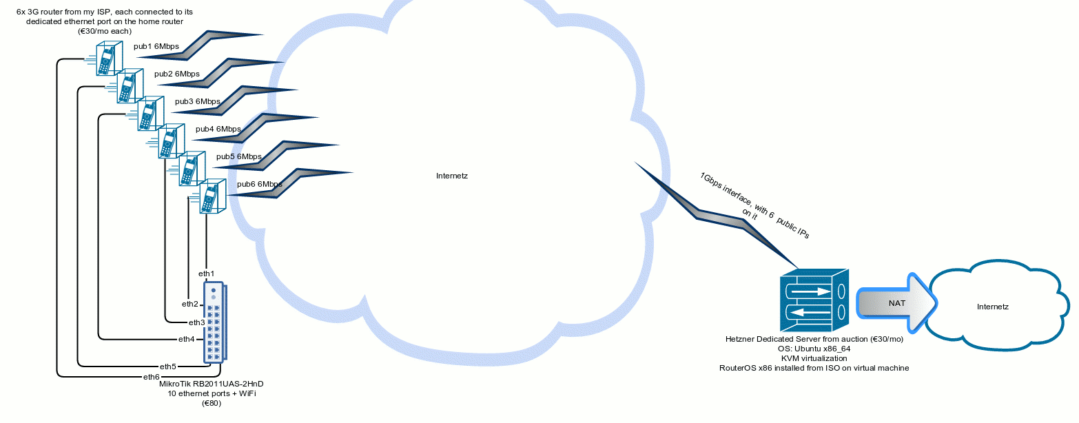
Equipment used
- 6x 3G router that I got when subscribing to ISP’s service (€30/month each)
- to prevent confusion, we’ll simply call these “modems” in the rest of the article even though they are actually routing traffic
- 1x MikroTik RB2011UAS-2HnD (€80)
- We’ll call this one “router” in the rest of the article, even though all 8 devices are technically routers
- 1x Dedicated server from Hetzner (€27/month at their auction)
- This doesn’t do anything other than run our virtual machine
- FlexiPack and /29 subnet (€20/month)
- Installed Ubuntu and KVM virtualization on it
- 1x Virtual Machine with a routed public /29 network installed on the dedicated server above
- RouterOS x86 Level 4 license (€30)
- Installed RouterOS on that virtual machine
- We’ll call this one “concentrator” because it concentrates our VPN connections :-/
Setup explanation
In general, for bonding to even work bonded network interfaces have to be physically connected (directly or using a network switch). Considering that this is all done over the internet, bonding can’t work out of the box. To overcome this hurdle, we first need to make sure that there are some directly connected network interfaces to bond. The obvious thing would be to create some VPN between our router and concentrator and bond those VPN interfaces. But that doesn’t really work as expected for several reasons:
- I don’t have a static public IP
- I can’t get it on my type of service because my ISP has some boureaucratic nonsense and apparently doesn’t like taking my money
- I don’t even have access to the dynamic public IP allocated by the ISP on every reconnect
- That’s because my ISP doesn’t have ipv6 and is NAT-ing ipv4 for all mobile network users, so modems don’t even get a public IP.
Therefore, I can’t use any VPN tunnels that rely on public IPs unless I want to fiddle with scripting on every reconnect. Instead, I’ll just use some VPN that can traverse NAT (PPTP, OpenVPN…) Considering that I’ll be using this for all of my internet traffic including video streaming, I should minimize the use of compression and encryption because those cause havoc for any type of streaming by queueing and delaying packets while compressing or encrypting them. So, less is more when deciding which tunneling method to use - good old PPTP for the win!
After we have our PPTP tunnels, we should bond them. Oooops. Forgot that PPTP tunnels aren’t really bondable because they aren’t full blown ethernet type of interface. They operate on a higher networking level. So, to overcome this we need some virtual ethernet-type interfaces inside those VPN tunnels. Enter EoIP. EoIP is Mikrotik’s wonderful way of making ethernet tunnles on top of existing IP layer. Meaning, we create EoIP network interface on each side of every one of our 6 PPTP tunnels to get 6 full ethernet links on both our router and our concentrator. Once we have that, we can treat EoIP interfaces like any real ethernet interface, meaning that we can bond them too !
Once we have our 6 ethernet connections, we can easily bond them on each side. The resulting bond interfaces will operate as if they were one single connection but actually send traffic over all 6 interfaces.
Depending on the type of bonding algorithm used, the combined throughput on the bonding interface will be greater than the throughput of any single link.
I’m not going to create copy-paste commands for MikroTik in this article. Instead, I’ll try to describe everything in details so that it can be easily replicated on other platforms, such as any Linux-based distribution or specialized networking platforms (Cisco, OpenWRT, ZeroShell, Juniper…)
Interface overview
I’ve connected each “modem” to one ethernet port on the home router. It’s perfectly fine to physically connect them any way that you want to, as long as internet is accessible from the home router via each link.
-
In my case, “modems” are actually all routers and are set to dial internet connection automatically and provide internet access without any user intervention.
-
Modems have IPs 192.168.101.1, 192.168.102.1, etc.
-
eth1-6: ethernet interface on the home “router” to which modems are connected; ip addresses assigned to the interface are 192.168.101.254, 192.168.102.254 ,etc.
-
vpn1-6: pptp interface on the home router. Each vpn tunnel has 1 IP address automatically assigned by the concentrator when PPTP connection gets established.
-
VPN Client-side addresses: 192.168.128.101-192.168.128.106
-
VPN Server-side addresses: 192.168.128.201-192.168.128.206
-
eoip1-6: EOIP (virtual ethernet) interfaces.
-
These don’t have any IPs assigned to them. They are virtual interfaces established inside each PPTP tunnel to give us full ethernet interfaces to bond.
-
bndSrv: Bond interface that we’re creating on the vpn concentrator side
-
bndCli: Bond interface that we’re creating on our home router
Configuration
Step 0:
- We need to configure our “concentrator” as PPTP server and an internet gateway for PPTP clients; meaning profiles, username/password, routing NAT, etc. I won’t be covering this in this article.
- We need to configure our modems to work and you know… NAT/route traffic. I won’t be covering this either.
Step 1: ISP Links
As previously mentioned, I’m using 6 3G routers. For all intents and purposes these behave like any other crappy WiFi router that one would get from their ISP. Though we’re using 3G links in this article, these can actually be any kind of link. So, ADSL, cable, fiber… anything. And they don’t even have to be the same, so we can mix i.e. cable and 3G. One thing to keep in mind is that our performance will vary according to the links used. So, if we mix fiber and 3G performance will vary depending on the bonding mode that we select later on. So, if we’re looking to use 3G only when fiber is overloaded or down, we can. But more on that later.
The point is to connect all of our “modems” to the home router in some way, set up isolated networks for every “modem” in order to avoid any networking conflicts and we’re good to go. In my case, it means connecting each modem’s ethernet port to one of home router’s ethernet ports and configuring IP addresses on modems and home router to actually have networking all set up. I’m using static IPs for this because I really don’t want my home router to wait for modems’ DHCP to allocate IP before bringing the interface up after i.e. modem or router reboot.
I’ve connected each “modem” to one ethernet port on the home router. Modems have IPs: 192.168.101.1, 192.168.102.1, etc. Home router’s ethernet ports eth1-6 have IPs: 192.168.101.254, 192.168.102.254 ,etc. Notice that I’ve used /24 network in every case in order to make the configuration easier by not having to remember any subnets.
Step 2: Static Routes
Considering that we want every PPTP tunnel to go over a different underlying ISP link, we need to configure static routes. So, if our “concentrator” has public IPs 8.8.8.1 , 8.8.8.2 , etc. we need to create a static route for each one of those public IPs and set its gateway to match the “modem” gateway IP. I.e. on RouterOS we can do it like this:
/ip route
add check-gateway=ping distance=1 dst-address=8.8.8.1/32 gateway=192.168.101.1
add check-gateway=ping distance=1 dst-address=8.8.8.2/32 gateway=192.168.102.1
add check-gateway=ping distance=1 dst-address=8.8.8.3/32 gateway=192.168.103.1Step 3: PPTP tunnels
Assuming that we’ve configured the “concentrator” to work as a PPTP server, we need to create 6 PPTP clients on the home router. Note: if your ISP is providing you with static IPs on underlying links, you can completely skip over this step, use your modems in bridge mode and configure static IPs on your home router. Unfortunately, I can’t so I need to sacrifice some performance and introduce this complexity to get static IPs to use when establishing EOIP links.
On Mikrotik configuring a PPTP client is really simple. Also, feel free to use the same username and password for all of these tunnels, as long as you’ve configured that user’s profile on the concentrator to allow multiple links.
/interface pptp-client
add allow=pap connect-to=8.8.8.1 disabled=no max-mru=1492 max-mtu=1492 mrru=1600 name=vpn1 user=myname-1
add allow=pap connect-to=8.8.8.2 disabled=no max-mru=1492 max-mtu=1492 mrru=1600 name=vpn2 user=myname-2
add allow=pap connect-to=8.8.8.3 disabled=no max-mru=1492 max-mtu=1492 mrru=1600 name=vpn3 user=myname-3VPN Client-side addresses: 192.168.128.101-192.168.128.106 VPN Server-side addresses: 192.168.128.201-192.168.128.206
Depending on your platform of choice for the concentrator, you’ll need to configure this correctly. Potential problems to watch out:
- Make sure that your PTPP tunnel’s MTU is set correctly. I.e. if you’re on ADSL, you’ll probably have to scale this down to 1492 bytes.
- Make sure to enable MRRU (not MRU but MRRU !) - it will allow packets larger than the MTU to be split and recombined on PPTP level. That way even if you mess something up when setting MTU on EOIP level, it will still work but much slower than it should.
- In case you can’t set MRRU, don’t worry; just make sure to configure MTU and MRU correctly, as well MSS mangling firewall rules.
Now, if we configured everything correctly we should have 6 PPTP tunnels established and running just fine. Each side of that tunnel (concentrator and home router) has 6 interfaces - concentrator has 6 dynamic PPTP interfaces, and home router has 6 persistent PPTP “interfaces”. vpn-1 tunnel has a client side IP 192.168.128.101 and server side IP 192.168.128.201 .
We will now create an EOIP tunnel named eoip1 that works inside the PPTP tunnel named vpn1. We need to pay special attention to the correct tunnel-id parameter because it has to match on both sides in order to avoid conflicts (i.e. if we create multiple tunnels with same IPs).
On home router:
/interface eoip
add clamp-tcp-mss=no keepalive=20s local-address=192.168.128.101 name=eoip1 remote-address=192.168.128.201 tunnel-id=101
add clamp-tcp-mss=no keepalive=20s local-address=192.168.128.102 name=eoip2 remote-address=192.168.128.202 tunnel-id=102
add clamp-tcp-mss=no keepalive=20s local-address=192.168.128.103 name=eoip3 remote-address=192.168.128.203 tunnel-id=103
On the concentrator
/interface eoip
add clamp-tcp-mss=no keepalive=20s local-address=192.168.128.201 name=eoip1 remote-address=192.168.128.101 tunnel-id=101
add clamp-tcp-mss=no keepalive=20s local-address=192.168.128.202 name=eoip2 remote-address=192.168.128.102 tunnel-id=102
add clamp-tcp-mss=no keepalive=20s local-address=192.168.128.203 name=eoip3 remote-address=192.168.128.103 tunnel-id=103
Note that we don’t care about eoip tunnels’ MTU here. That’s because bonding them will override this value and set it to whatever we choose for the aggregated bond interface.
Step 5: Bonding
And finally, the voodoo. Note. if you can get static public IPs on both concentrator and “home router”, you can skip all the steps and start from here. Lets remember that the use case here is multiple wan link aggregation. Meaning, I want a fast reliable internet connection for my home. I’ll be using it for basically all the standard needs - surfing, video conferencing, VOIP, watching movies, torrenting and everything else that a typical home office would do. Use case it the primary thing to consider when thinking about bonding methods because as previously mentioned, there are several methods possible and they all come with different advantages and downsides.
For this specific use, there are only 2 bonding methods that would aggregate bandwidth without wasting any links on redundancy. Those are balance-rr and balance-xor. I’ll first show what I’ve chosen, and explain why and other modes below.
After a lot of testing, I’ve decided to use balance-xor method. To do that, I’ve created a new bond interface on both the concentrator and home router, added all these eoip links to them as slaves, and chosen balance-xor with Layer 3 and 4 hashing on both sides. This way, connections are distributed across all slaves. Note: Make sure that you lower the bond interface’s MTU. I’ve set mine to to 1388. If you leave MTU at 1500, it will still work (because underlying PPTP tunnels have MRRU 1600) but it will work a lot slower than it should because almost all packets are being split in two on PPTP level and reassembled on the receiving end. That’s because they’re exceeding PPTP’s MRU limit. Naturally, lower MTU means that you’ll have to configure MSS mangling for TCP SYN flags on your firewall.
After configuring the bond interface, EOIP interfaces should show up as slaves and the only thing remaining is assigning an IP address to each bond interface, configuring NAT and set it as default route.
End Results
… will vary based on the use case.
As previously mentioned, maximum speed of each one of the 6 links that I’m using is ~8Mbps, but in reality it’s usually around 6Mbps. However, those links are quite unreliable and often drop down to ~2Mbps, so with 6 of them I’ll usually have like 3 links at 6Mbps while others will be anywhere between 2Mbps and 5Mbps.
Therefore, the theoretical limit that I can hit is 6x8Mbps = 48Mbps. But that’s only theoretical. It will almost always be less than that, depending on current link speeds and the workload.
In balance-rr mode I’ve been able to reach those limits less than 10% of the time.
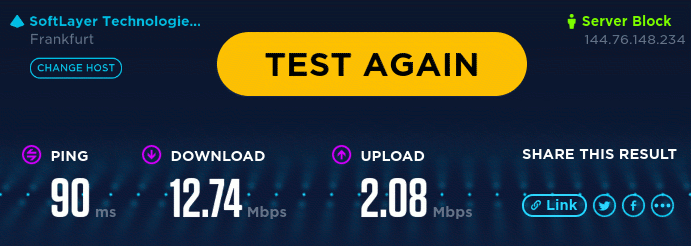
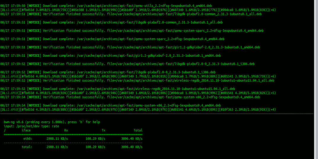
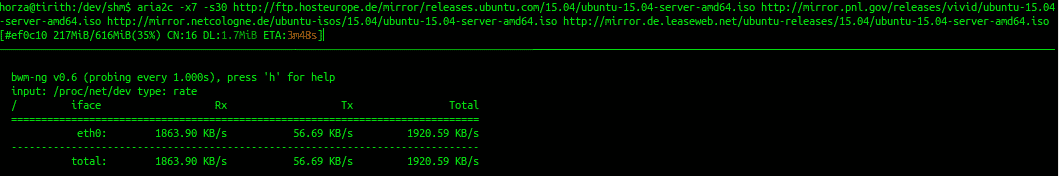
As we can see in the screenshots below (balance-rr mode) , different workloads give us different resutls.
Oookla’s Speedtes will measure only 12Mbps because it’s done using a single TCP connection which requires retransmitions in case of packets received out of order. Considering that we’re using balance-rr mode which in fact causes packets to be received out of order, we are basically wasting 60% of available bandwidth to retransmit those packets.
2nd screenshot is apt-fast. A wonderful apt helper application for downloading Debian/Ubuntu/Mint… system updates from multiple update mirrors at once. So, if we set it to download using 11 concurrent connections and provide it with enough mirrors, we get some 25Mbps. We are still wasting a lot of available bandwidth on TCP retransmission, but at least we’re using multiple connections to avoid transmission blocking.
3rd screenshot is Aria - a standard console download manager for Debian/Ubuntu. You’ll notice that I’ve set -x (connections per server) to 7 and -s (total connections) to 30 and provided it with 3 mirrors in order to avoid server-imposed hrottling. This allowed me to download at some 16Mbps. Again, it’s all TCP so a lot of overhead caused by out of order packets
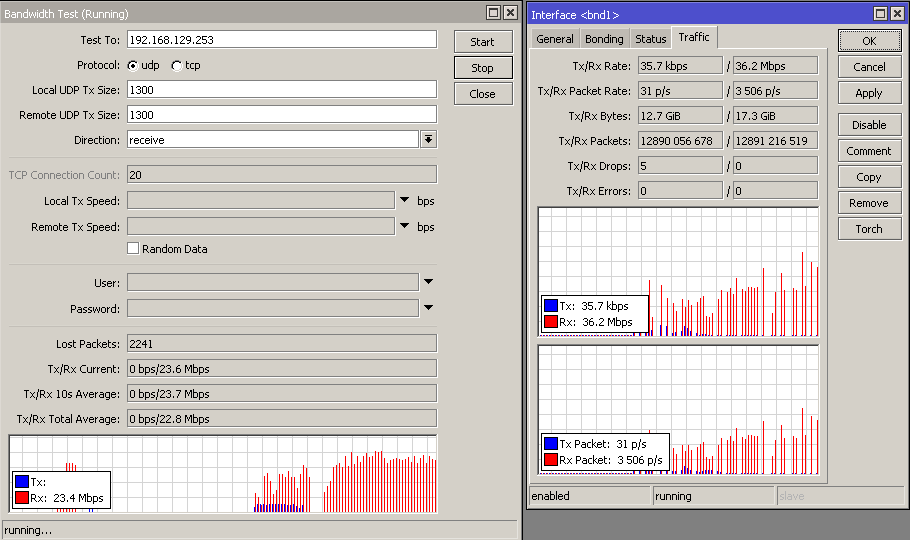
The last screenshot shows Mikrotik’s bandwidth test integrated in their RouterOS. This is a UDP test between the concentrator and my home router and as we can see, an average 24Mbps UDP download, which is quite nice for these unreliable links.
It’s worth mentioning that I’d be quite happy with 12Mbps single TCP connection speed and just leave it at that. However, this is a rare case because if one underlying 3g connection drops to say 512Kbps (spikes happen often), my total aggregated throughput will be 6x512Kbps TCP throughput will be 3Mbps. And that’s not per i.e. one TCP connection, but the total maximum bandwidth. Considering that these 3g links are quite unreliable so it happens quite often.
In balance-xor mode however, things are quite different. Unfortunately, I can’t really provide screenshots at this point because … well… my 3g has been really slow for the past week or so due to ISP problems. But the differences are as described - higher aggregated throughput for multiple TCP connections, lower aggregated throughput for UDP (limited by 1 underlying link’s speed) and waaaay better user experience. That’s because mosts sites use CDNs to off-load traffic, so everything loaded simply works faster by default because multiple connections are used download content.
The only problem with balance-xor that I can see is the future. Web has slowly but surely stepped into http/2 protocol. This means that all sites are moving towards SPDY (or generic connection multiplexing in http/2 RFC). This means that instead of opening multiple TCP connections to download content of one website from one server (browser connection pipelining), HTTP/2 protocol encourages use of a single encrypted TCP connection multiplexed to download content in parallel. This is also bad for balance-rr because protocol encryption only makes the packets out of order retransmission more visible to the end user. So, lets hope that projects such as Facebook’s internet.org , Google’s Loon and SpaceX’s satellite internet gain more momentum and finally make affordable high speed internet globally available.
A bit more on bonding in layman terms
balance-rr
-
Advantages
- Fastest “raw” speed
- Highest “raw” throughput possible
- Aggregated bandidth will be a sum of all the underlying bond members’ bandwidths, but only effective if the traffic is resillient to out of order packets.
- Works by distributing packets (layer 2), and not just connections (layer 3). Effectively, this means that it can split a single (TCP) connection across multiple links, thus aggregating bandwidth on packet level, and not just distributing multiple connections across bond members.
- High(est?) level of redundancy with virtually no overhead - even if all but one bond members are down, it will still work and will only lose packets until link monitoring figures that the link is down. For all home/office intents and purposes, users will notice that the link speed has dropped, and basically all connections (even VPN!) will keep on working; TCP will just retransmit lost packets and won’t break.
-
Disadvantages
- Any given connection (think TCP download) is limited by the speed of the slowest bond member. So, if one bond member has 1Gbps throughput and another member has 10Mbit throughput, our TCP connection will actually be limited to only 20Mbit (10Mbit on the slow link and only 10Mbit of the 1Gbps link). That’s because this bonding mode uses a literal round-robbin algorythm to distribute traffic across bond members.
- Packets are received out of order. That’s because splitting single connection’s packets across multiple links of varying speed will cause packets sent first to be received 2nd or 3rd or whichever. This might not be such a huge problem if we’re bonding only 2 reliable symetrical links, such as 2x1Gbps in a stable server room environment. The chance of packets arriving to destination out of order there is minimal and retransmission is cheap.
- Howerver, it’s a complete mess when bonding 6 links with varying and high latency (3g). Also, the more underlying links we have, the chance of receiving packets out of order grows exponentially, thus increasing the number of packet retransmissions. Therefore single TCP connections are in my case slower when aggregated than they are on a single link. Naturally, I can still have more links a a higher total throughput with 6 bonded links than just a single link. But it’s kinda annoying to see download limited to like 2Mbps when downloading OS updates or anything using a browser, knowing that raw speed is 40Mbps.
- Those 2 downsides result in aggregate speed effectively varying based on the maximum speed of the slowest link
- more links = more chance of out of retransmit overheads = lower effective speed
- bigger the bond member link difference in speed, the more packets received out of order = more retransmits = lower effective speed
-
Use cases
- Perfect for broadcasts or unicasts of any kind
- SIP server
- CCTV server
- Torrent seeding via UDP
- Video broadcast of any kind (as long as it’s actually a broadcast/multicast/unicast and not i.e. flash streaming via TCP :D)
- Perfect for any traffic that allows packets to be received out of order
balance-xor
-
Advantages
-
Same as balance-rr minus splitting traffic on packet level. Meaning that it splits traffic only per layer 3 and layer 4 identifiers. This means that it can take multiple TCP connections between the same hosts and move them across different bond members. It can also “move” the same persistent TCP connection from one bond member to another. But it does not “split” a TCP connection across multiple bond members. Meaning that single connection’s packets are always received in order, thus ensuring maximum throughput that the bond member can provide. In case there are multiple bond members of different speed, one TCP connection will have the throughput of one underlying link (i.e. 10Mbps) while the other one that’s bound to 1Gbps link will have 1Gbps speed.
-
(Most?) Efficient use of multiple asymetric bond members because the faster link will actually get more workload than the slower one
-
Aggregated bandidth will be a sum of all the underlying bond members’ bandwidths, but only effective if traffic is split across multiple connections
-
Very little resource overhead for any type of traffic
-
A lot more established connections possible than with balance-rr
-
Disadvantages
-
Not efficient for splitting traffic on packet level
-
Any single connection will be limited by the speed of it’s assigned underlying bond member. In contrast to bonding-rr where a connection can be split across multiple bond members and have its speed increased that way i.e. UDP connection will be limited by single bonding member’s speed, whereas in bonding-rr it can be a sum of all bonding members
-
Have to use multiple connections to utilize all the available bandwidth of all bonding members
-
Use cases
-
Well… anywhere where you would use balance-rr but don’t have symetrical and stable underlying bond members Such as my use case where I’ve got 3g connections with high and varying latency (60ms) with up to 2s of rtt deviation
-
Office WAN links. i.e. if you’ve got a 30Mbps primary cable link, and a 20Mbps ADSL backup link. It’s perfectly fine to bond them this way. You get fantastic redundancy out of the box, and those 20Mbps get used all the time, not just during outages. Naturally, there are easier and less expensive ways to acchieve this, such as PCC queueing but your connections will break in case of an outage, whereas bonding will keep them running and just fail over to the other link.
-
Same goes if you’ve got faster links, though if it’s just redundancy you’re looking for, other bonding modes might be a wiser choice - especially if you’ve got multiple failover links and would like to prioritize them.
Final words
Massive thanks to Dino Vizinger for thinking this through, testing it with me and peer reviewing it.
Pay attention to MTU. Always pay attention to damn MTU.
Always avoid contracts for any Telecom/ISP services.
Never buy good-looking network equipment or hardware. Best hardware always looks like it time-traveled from the ’60s.